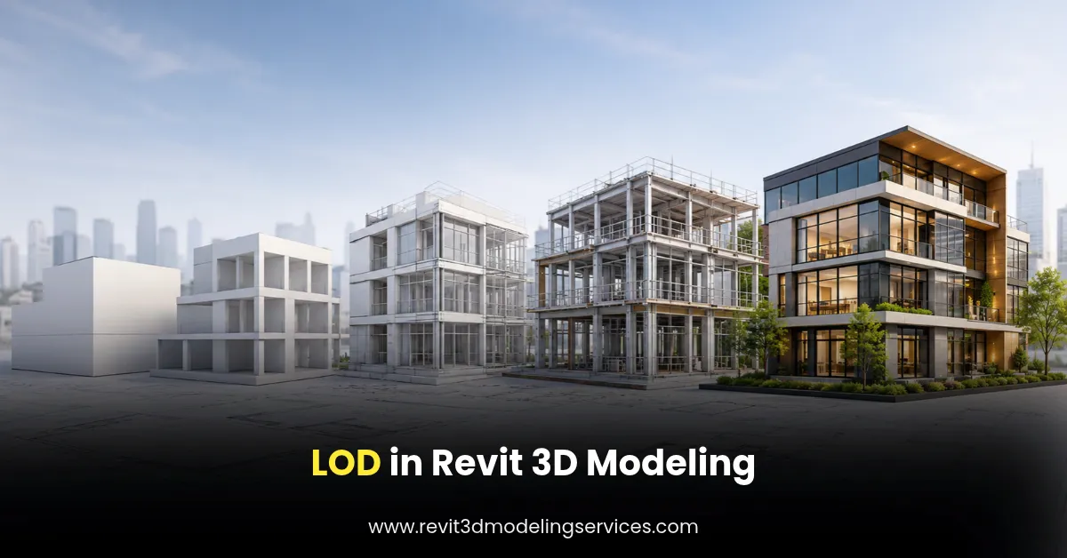
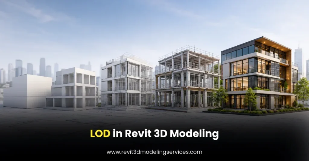
LOD (Level of Development) plays an important role in Revit 3D Modeling because it defines how much detail, accuracy, and information a BIM model should contain at different project stages. For architects, engineers, and contractors using Revit BIM Modeling Services, understanding LOD helps establish clear modeling expectations, improve coordination, and avoid unnecessary modeling work.
A Revit model does not need the same level of detail throughout the entire project. Early design may require basic geometry, while construction and fabrication require more accurate dimensions, component information, and specifications. Choosing the right LOD ensures that the model supports its intended purpose.
What Is LOD in Revit 3D Modeling?
LOD stands for Level of Development. It describes the reliability, graphical representation, and information available for BIM elements within a model.
In Revit, LOD determines how accurately building components represent their real-world counterparts. For example, an architectural wall at an early design stage may appear as a simple mass, while a more developed wall model may include its layers, thickness, materials, openings, and relevant construction information.
LOD helps project teams understand what they can expect from a model and how they can use its elements for design, coordination, estimation, and construction.
Important: LOD does not simply mean adding more geometric details. It also considers how much reliable information a BIM element contains and whether project teams can depend on that information for specific decisions.
Different Levels of Development (LOD) in Revit
The commonly used LOD framework includes LOD 100, 200, 300, 350, 400, and 500. Each level represents a different stage of model development and supports specific project requirements.
1. LOD 100 – Conceptual Design
LOD 100 represents the initial design stage. Building elements appear as conceptual shapes, masses, or approximate volumes rather than fully developed components.
Typical applications:
- Initial building concepts and massing studies.
- Preliminary area and volume calculations.
- Early design discussions.
- Feasibility studies and project planning.
Example: An architect may create a basic building mass in Revit to understand the overall building height, approximate floor area, and general layout before developing detailed architectural elements.
2. LOD 200 – Schematic Design
LOD 200 introduces approximate geometry, quantities, sizes, shapes, and locations. Elements become more recognizable, but their dimensions and specifications may still be approximate.
Typical applications:
- Schematic architectural modeling.
- Preliminary structural layouts.
- Early MEP system planning.
- Initial design coordination.
Example: A structural column may appear in its approximate position with an estimated cross-section, while an HVAC duct may show its general route without final fabrication-level details.
3. LOD 300 – Detailed Design
LOD 300 provides accurately defined geometry, dimensions, quantities, and locations. Project teams can use the model for detailed design development, coordination, and construction documentation.
Typical applications:
- Detailed architectural and structural modeling.
- MEP system layouts.
- Design coordination.
- Construction drawings and documentation.
Example: A concrete column can include its actual dimensions and location, while an architectural door can have defined dimensions, orientation, and relevant specifications.
4. LOD 350 – Construction Coordination
LOD 350 adds information about how building elements connect and interact with other components. It includes interfaces, supports, connections, and coordination requirements.
Typical applications:
- MEP clash detection and coordination.
- Structural and architectural interface checks.
- Equipment clearance reviews.
- Construction coordination.
Example: An HVAC duct model may include its relationship with structural beams, hangers, supports, and nearby electrical or plumbing systems. This helps teams identify potential installation conflicts before construction.
5. LOD 400 – Fabrication and Installation
LOD 400 provides detailed information required for fabrication, assembly, and installation. Components include precise dimensions, connections, and manufacturing-related information according to the project scope.
Typical applications:
- MEP fabrication modeling.
- Steel detailing.
- Prefabrication planning.
- Installation drawings and shop drawings.
Example: An MEP contractor may require detailed ductwork with fittings, connections, dimensions, and fabrication information to support off-site manufacturing and on-site installation.
6. LOD 500 – As-Built Model
LOD 500 represents verified existing or installed conditions. The model reflects actual field conditions based on appropriate verification and project documentation.
Typical applications:
- Facility management.
- Building operations and maintenance.
- Renovation and refurbishment.
- Asset information management.
Example: After construction, a facility owner may use an LOD 500 model containing verified equipment locations, installed systems, and relevant asset information to support building maintenance.
Note: LOD 500 is not simply a more detailed version of LOD 400. It focuses on verified as-built conditions rather than fabrication-level geometry.
LOD Comparison: Which Level Should You Choose?
The right LOD depends on project objectives, design maturity, construction requirements, and the information contractors or consultants need from the model.
| LOD | Model Development | Common Application |
| LOD 100 | Conceptual representation | Feasibility and planning |
| LOD 200 | Approximate geometry | Schematic design |
| LOD 250 | Intermediate development | Early coordination |
| LOD 300 | Accurate design geometry | Design documentation |
| LOD 350 | Detailed interfaces | Construction coordination |
| LOD 400 | Fabrication-level details | Fabrication and installation |
| LOD 500 | Field-verified conditions | Facility management |
Industry update: The BIMForum 2025 specification introduces LOD 250 as an optional intermediate level between LOD 200 and LOD 300. Project teams should confirm which specification and LOD definitions their contracts or BIM execution plans require.
How to Choose the Right LOD for Your Revit Project
Selecting an appropriate LOD before starting Revit modeling helps control project costs, modeling time, and coordination requirements. Consider these factors:
- Project stage: Conceptual projects may need LOD 100 or 200, while detailed design generally requires LOD 300.
- Project purpose: Choose LOD 350 for construction coordination and LOD 400 when fabrication information is required.
- Discipline requirements: Architectural, structural, and MEP components may require different development levels.
- Client expectations: Review project specifications, BIM execution plans, and required deliverables.
- Available information: Ensure drawings, dimensions, specifications, and site information support the requested LOD.
For example, in a commercial building project, architectural elements may require LOD 300, while mechanical ductwork and plumbing systems may need LOD 350 to support coordination with structural elements. Modeling every component at LOD 400 would increase effort without necessarily improving the project’s outcome.
This is why an element-by-element LOD matrix is useful. It identifies the required development level for each building system instead of assigning one level to the entire Revit model.
Common LOD Mistakes to Avoid in Revit Modeling
Even experienced project teams can face problems when they do not define LOD requirements clearly.
- Confusing LOD with visual detail: A visually complex model does not automatically represent a reliable or accurate model.
- Using one LOD for every discipline: Architectural, structural, and MEP components may have different modeling requirements.
- Ignoring coordination requirements: Missing connections, clearances, and interfaces can create construction conflicts.
- Overmodeling components: Adding unnecessary details increases modeling time and file complexity.
- Skipping model verification: Teams should check dimensions, locations, parameters, and model information against approved project references.
A practical approach is to establish an LOD matrix during project planning and review it at each major delivery milestone. This helps modelers, BIM coordinators, engineers, and contractors maintain consistent expectations.
How Professional Revit BIM Modeling Services Support LOD Requirements
Professional Revit BIM Modeling Services help AEC companies develop models according to project-specific LOD requirements. The process typically includes drawing review, model development, discipline coordination, quality checks, and final delivery.
At Revit3DModelingServices, we understand that every project has different modeling requirements. For example, a residential architectural project may require LOD 300 for design documentation, whereas a commercial MEP project may need LOD 350 for multidisciplinary coordination.
Our approach focuses on:
- Developing models according to agreed LOD requirements.
- Maintaining accurate geometry and component information.
- Following client-specific BIM standards and Revit templates.
- Reviewing model quality before final delivery.
- Supporting revisions according to the agreed project scope.
These practices help project teams receive Revit models that match their intended applications rather than models containing unnecessary details.
Conclusion
Understanding LOD in Revit 3D Modeling helps architects, engineers, contractors, and BIM professionals establish clear modeling requirements at every project stage. From conceptual LOD 100 models to fabrication-ready LOD 400 and verified LOD 500 models, each level serves a different purpose. Selecting the right LOD improves coordination, controls modeling effort, and supports better project delivery.
If you are planning a new BIM project, define your required LOD, project scope, and deliverables before starting the modeling process.
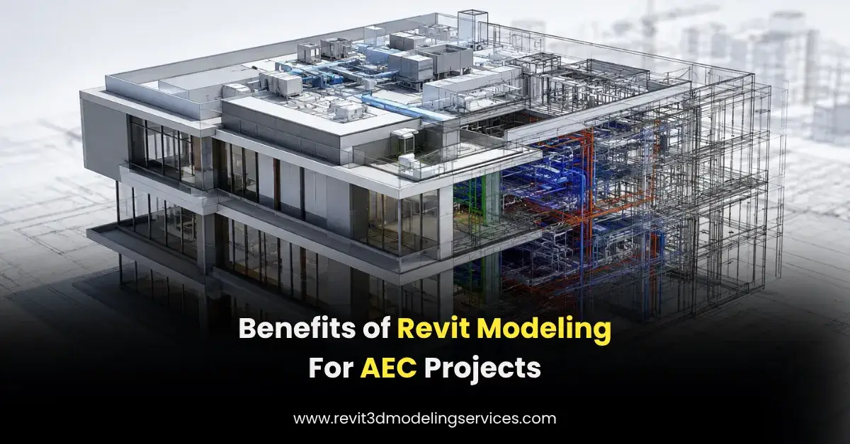
Also read: Benefits of Revit 3D Modeling for AEC Projects
Frequently Asked Questions
1. What does LOD mean in Revit 3D Modeling?
LOD means Level of Development. It defines the reliability, geometry, and information associated with individual BIM elements at different stages of a project.
2. What is the difference between LOD 300 and LOD 350?
LOD 300 provides accurately defined geometry, dimensions, and locations. LOD 350 additionally represents interfaces and relationships with adjacent or dependent building elements for construction coordination.
3. Which LOD is best for construction projects?
LOD 300 is commonly used for detailed design, while LOD 350 supports construction coordination. LOD 400 is appropriate when fabrication and installation details are required.
4. Is LOD 500 more detailed than LOD 400?
Not necessarily. LOD 400 focuses on fabrication and assembly information, whereas LOD 500 represents verified installed conditions. They serve different purposes.
5. How does LOD affect Revit modeling costs?
Higher development requirements generally require more modeling time, technical information, coordination, and quality checks. Actual costs depend on project size, complexity, available information, and deliverables.